PTZ Instructions for Use
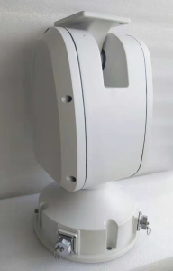
Thank you for choosingBenThe company's products, please read the user manual carefully before using this product. This manual will provide you with correct installation and usage instructions.
I. Technical specifications
technology technique refer to mark say Ming | |
input voltage | DC24V 4.2A |
Power | ≤75W |
horizontal speed | 0.1°~25°/s |
vertical speed | 0.1°~10°/s |
Rotation range | level: 360°continuous rotation vertical: -80°~+60° |
Preset position | most60a |
Communication method | RJ45 network port |
Communication protocol | Pelco-D |
maximum load | 8 kg |
Carrying mode | top load |
working temperature | -40℃~+55℃ |
Storage temperature | -40℃~+65℃ |
Rainproof | Moderate rain-Heavy rain |
Material | Body: aluminum alloy |
Pan-Tilt Systemsweight | ≤10kg |
baud rate | 9600 |
address | 1 |
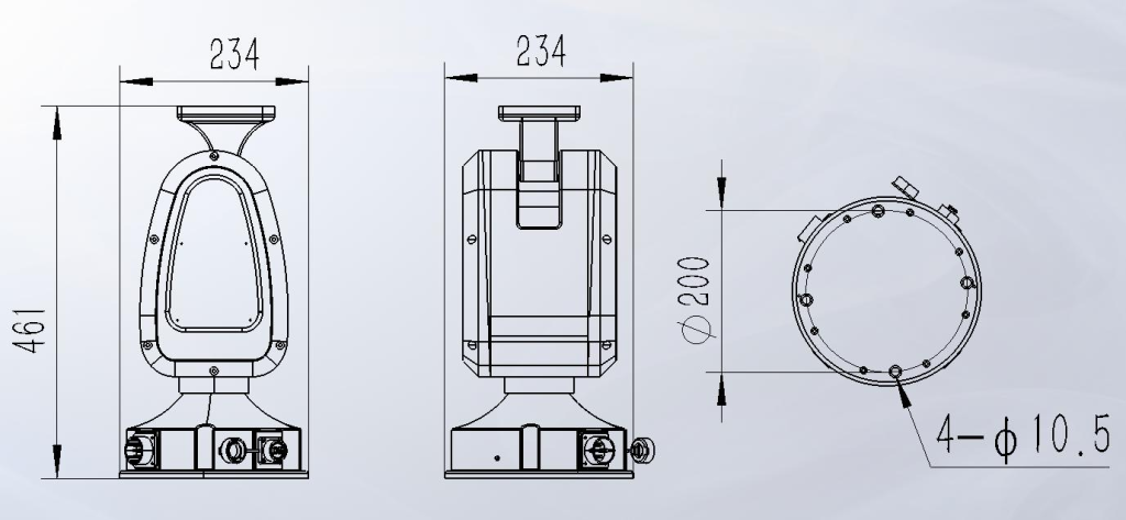
PTZ size | L 234mm width234mm height461mm |
PI address | 192.168.1.200. |
Default gateway | 192.168.1.1 |
conductive ring | network signal |
Others | No self-test on power-on level |
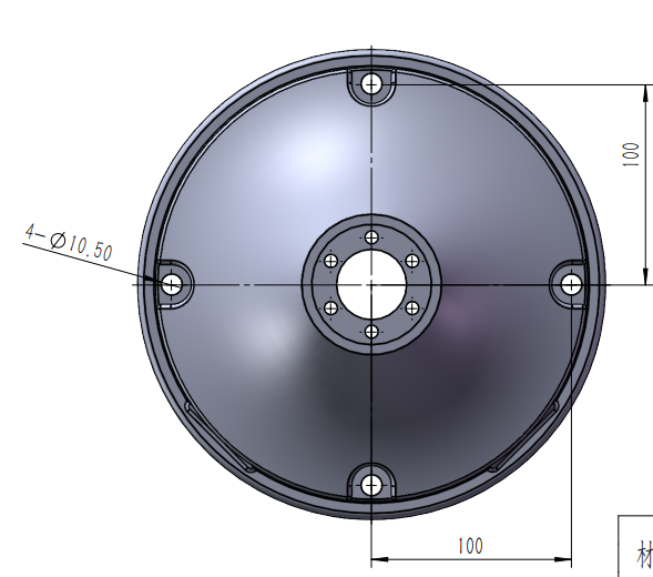
II. Base hole location map
III. PTZ wiring definition
The pan/tilt base (reverse) is large4 core |
| The gimbal base is small12 core | |
1 | empty | 1 | red blue① Network cable to the PTZ control panel to network cable |
2 | grounded black | 2 | orange powder② Network cable to connect to the Yuntai control panel to the network cable |
3 | DC24+ | 3 | gray purple③ Network cable to the PTZ control panel to network cable |
4 | DC24V- | 4 | white light blue⑥ Network cable: Tongyuntai control panel to network cable |
|
| 5 |
|
|
| 6 |
|
|
| 7 |
|
|
| 8 |
|
|
| 9 |
|
|
| 10 |
|
|
| 11 |
|
|
| 12 |
IV. Overall size of the gimbal
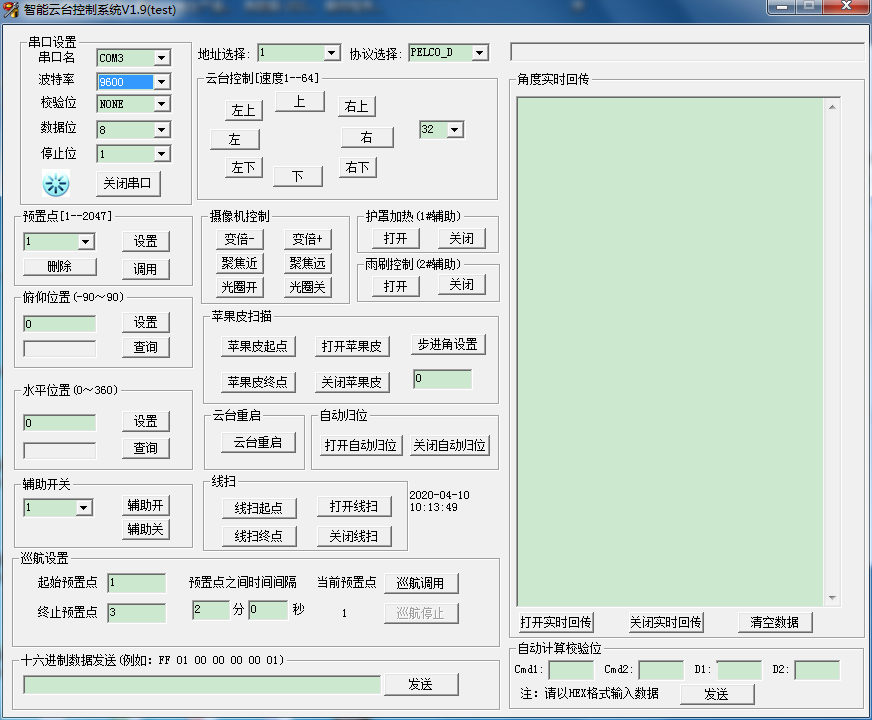
The following commands are extended commands for the gimbal, providing more advanced control commands. The specific control commands are as follows: Extended control commands
command
Bytes3
Bytes4
Bytes5
Bytes6
Description
query data open
0X00
0X03
0X00
settingsPreset point 200
Default status query method
Query data gateway
0X00
0X07
0X00
callPreset point 200
When querying data, return the real-time status of the information
Auto follow (proportional zoom) off
0X00
0X07
0X00
callPreset position 212
Turn off the zoom linkage(Lens control board support is required)
Automatically follow initialization
0X00
0X05
0X00
DeletePreset position 212
The speed level after initialization is1 level(Lens control board support is required)
Remote reboot reset
0X00
0X07
0X00
callPreset position 215
After receiving the command, the gimbal will be reset as a whole and then powered off and restarted.
Scan speed level switching
0X00
0X07
0X00
callPreset position 218
Speed levels are divided into7 levels are divided into speed levels, the slowest 01, 0D, 1A, 27, 34, the fastest 3F. Total 6 files. When the gimbal receives this command, it will switch 1 gears at a time, switching in a circular manner. (All scanning speed levels are valid set by this command)
Scan speed level initialization
0X00
0X05
0X00
DeletePreset position 218
The initial speed level is3 level speed1A
Area scan enabled
0X00
0X07
0X00
callPreset position 219
Perform intra-area round-trip scanning within the two set points.
Area scan off
0X00
0X05
0X00
DeletePreset position 219
Area scan setting starting point
0X00
0X03
0X00
settingsPreset position 219
Area scan setting end point
0X00
0X03
0X00
settingsPreset position 220
settingstrack scanstarting point
0X00
0X03
0X00
settingsPreset position 221
Set the current position as the starting point of the scan
settingstrack scanStarting point and end point
0X00
0X03
0X00
settingsPreset position 222
Set the current position as the scanning end point
Track scan on
0X00
0X07
0X00
callPreset position 221
Turn on trajectory scanning. During the scanning process, the trajectory scanning will run in a clockwise and counterclockwise cycle according to the set starting point and end point.
track scan off
0X00
0X05
0X00
DeletePreset position 221
Stop closing track scan
Set the starting point for apple peel scanning
0X00
0X03
0X00
settingsPreset position 223
Current location(starting point<end point)
Set the end point of apple peel scanning
0X00
0X07
0X00
callPreset position 223
Current location (starting point<end point)
Set the apple peel stepping angle
0X00
0X03
0X00
settingsPreset position 224
Step angle cycle switching:1°, 2°, 3°, 5°, 10°, total 5 files. When the gimbal receives this command, it will switch 1 gears at a time, and 5 gears will be switched cyclically.
Apple peel scanning is enabled
0X00
0X07
0X00
callPreset position 224
When turned on, each rotation will increase according to the step angle and continue to run until it reaches the end position, and then continue to run from the starting point.
Apple Peel Scanning Closed
0X00
0X05
0X00
DeletePreset position 224
Stop scanning after closing
Apple peel step angle initialization
0X00
0X05
0X00
DeletePreset position 225
When the gimbal receives this command, the stepping angle of the apple peel returns toThe 1 file is 1°
Automatic line scan
0X00
0X07
0X00
callPreset position 239
When the gimbal receives the automatic line scan command, the gimbal rotates horizontally clockwise at a speed related to the cruising speed, and stays at the current operating position vertically.
Set left limit
0X00
0X03
0X00
settingsPreset position 251
Set the current position as the left limit
Set right limit
0X00
0X03
0X00
settingsPreset position 252
Set the current position to the right limit
Set upper limit
0X00
0X03
0X00
settingsPreset position 253
Set the current position as the upper limit
Set lower limit
0X00
0X03
0X00
settingsPreset position 254
Set the current position as the lower limit
Start limit scan
0X00
0X07
0X00
callPreset position 251
Enable limit scan function
Turn off limit scan
0X00
0X07
0X00
callPreset position 252
Stop limit scan function
Cruise speed set to high speed
0X00
0X07
0X00
callPreset position 236
speed set to34
Cruise speed set to medium speed
0X00
0X07
0X00
callPreset position 237
speed set to1A
Cruise speed setting low speed
0X00
0X07
0X00
speed set to01
Set cruise time
0X00
0X07
0X00
callPreset position 229-235
Call preset position229-235 respectively corresponds to the set cruise time 5s, 10s, 20S, 30s, 60s, 120s, 240s
Execute cruise line1-4 strips
0X00
0X07
0X00
callPreset position 225-228
callThe 225-228 preset operations respectively correspond to the cruise line 1-4 operations. Each cruise line patrols 16 preset points, and no action will be performed on empty preset points.
Specific implementation:
cruise line1 contains the preset point 1-16;
cruise line2 contains the preset point 17-32;
cruise line3 contains the preset point 33-48;
cruise line4 contains the preset point 49-64;
command | Bytes3 | Bytes4 | Bytes5 | Bytes6 | Description |
query data open | 0X00 | 0X03 | 0X00 | settingsPreset point 200 | Default status query method |
Query data gateway | 0X00 | 0X07 | 0X00 | callPreset point 200 | When querying data, return the real-time status of the information |
Auto follow (proportional zoom) off | 0X00 | 0X07 | 0X00 | callPreset position 212 | Turn off the zoom linkage(Lens control board support is required) |
Automatically follow initialization | 0X00 | 0X05 | 0X00 | DeletePreset position 212 | The speed level after initialization is1 level(Lens control board support is required) |
Remote reboot reset | 0X00 | 0X07 | 0X00 | callPreset position 215 | After receiving the command, the gimbal will be reset as a whole and then powered off and restarted. |
Scan speed level switching | 0X00 | 0X07 | 0X00 | callPreset position 218 | Speed levels are divided into7 levels are divided into speed levels, the slowest 01, 0D, 1A, 27, 34, the fastest 3F. Total 6 files. When the gimbal receives this command, it will switch 1 gears at a time, switching in a circular manner. (All scanning speed levels are valid set by this command) |
Scan speed level initialization | 0X00 | 0X05 | 0X00 | DeletePreset position 218 | The initial speed level is3 level speed1A |
Area scan enabled | 0X00 | 0X07 | 0X00 | callPreset position 219 | Perform intra-area round-trip scanning within the two set points. |
Area scan off | 0X00 | 0X05 | 0X00 | DeletePreset position 219 |
|
Area scan setting starting point | 0X00 | 0X03 | 0X00 | settingsPreset position 219 |
|
Area scan setting end point | 0X00 | 0X03 | 0X00 | settingsPreset position 220 |
|
settingstrack scanstarting point | 0X00 | 0X03 | 0X00 | settingsPreset position 221 | Set the current position as the starting point of the scan |
settingstrack scanStarting point and end point | 0X00 | 0X03 | 0X00 | settingsPreset position 222 | Set the current position as the scanning end point |
Track scan on | 0X00 | 0X07 | 0X00 | callPreset position 221 | Turn on trajectory scanning. During the scanning process, the trajectory scanning will run in a clockwise and counterclockwise cycle according to the set starting point and end point. |
track scan off | 0X00 | 0X05 | 0X00 | DeletePreset position 221 | Stop closing track scan |
Set the starting point for apple peel scanning | 0X00 | 0X03 | 0X00 | settingsPreset position 223 | Current location(starting point<end point) |
Set the end point of apple peel scanning | 0X00 | 0X07 | 0X00 | callPreset position 223 | Current location (starting point<end point) |
Set the apple peel stepping angle | 0X00 | 0X03 | 0X00 | settingsPreset position 224 | Step angle cycle switching:1°, 2°, 3°, 5°, 10°, total 5 files. When the gimbal receives this command, it will switch 1 gears at a time, and 5 gears will be switched cyclically. |
Apple peel scanning is enabled | 0X00 | 0X07 | 0X00 | callPreset position 224 | When turned on, each rotation will increase according to the step angle and continue to run until it reaches the end position, and then continue to run from the starting point. |
Apple Peel Scanning Closed | 0X00 | 0X05 | 0X00 | DeletePreset position 224 | Stop scanning after closing |
Apple peel step angle initialization | 0X00 | 0X05 | 0X00 | DeletePreset position 225 | When the gimbal receives this command, the stepping angle of the apple peel returns toThe 1 file is 1° |
Automatic line scan | 0X00 | 0X07 | 0X00 | callPreset position 239 | When the gimbal receives the automatic line scan command, the gimbal rotates horizontally clockwise at a speed related to the cruising speed, and stays at the current operating position vertically. |
Set left limit | 0X00 | 0X03 | 0X00 | settingsPreset position 251 | Set the current position as the left limit |
Set right limit | 0X00 | 0X03 | 0X00 | settingsPreset position 252 | Set the current position to the right limit |
Set upper limit | 0X00 | 0X03 | 0X00 | settingsPreset position 253 | Set the current position as the upper limit |
Set lower limit | 0X00 | 0X03 | 0X00 | settingsPreset position 254 | Set the current position as the lower limit |
Start limit scan | 0X00 | 0X07 | 0X00 | callPreset position 251 | Enable limit scan function |
Turn off limit scan | 0X00 | 0X07 | 0X00 | callPreset position 252 | Stop limit scan function |
Cruise speed set to high speed | 0X00 | 0X07 | 0X00 | callPreset position 236 | speed set to34 |
Cruise speed set to medium speed | 0X00 | 0X07 | 0X00 | callPreset position 237 | speed set to1A |
Cruise speed setting low speed | 0X00 | 0X07 | 0X00 | speed set to01 | |
Set cruise time | 0X00 | 0X07 | 0X00 | callPreset position 229-235 | Call preset position229-235 respectively corresponds to the set cruise time 5s, 10s, 20S, 30s, 60s, 120s, 240s |
Execute cruise line1-4 strips | 0X00 | 0X07 | 0X00 | callPreset position 225-228 | callThe 225-228 preset operations respectively correspond to the cruise line 1-4 operations. Each cruise line patrols 16 preset points, and no action will be performed on empty preset points. Specific implementation: cruise line1 contains the preset point 1-16; cruise line2 contains the preset point 17-32; cruise line3 contains the preset point 33-48; cruise line4 contains the preset point 49-64; |